No products in the cart.
Shop all products

Solenoid Valve Specifications and Dimensions
people are viewing this right now
Guaranteed Safe Checkout

- Free worldwide shipping on all orders over $100
- Delivers in: 3-7 Working Days Shipping & Return
Call us at (650) 856-8833 or email us at Sales@StcValve.com.
Solenoid Valve Specifications and Dimensions: 2S025-050 Series
| Specifications |
|
|||||
| Valve Model | 2S025-1/4 | 2S035-1/4 | 2S040-3/8 | 2S050-1/4 | 2S050-3/8 | |
| Valve Type | 2 Way Normally Closed | |||||
| Action | Direct Acting | |||||
| Port Size (NPT) | 1/4″ | 1/4″ | 3/8″ | 1/4″ | 3/8″ | |
| Cv (Orifice) | 0.23 (2.5mm) | 0.5 (3.5mm) | 0.6 (4mm) | 1.0 (5mm) | 1.0 (5mm) | |
| Operating Pressure | 0 to 200PSI | 0 to 170PSI | 0 to 150PSI | 0 to 80PSI | 0 to 80PSI | |
| Operating Temperature | 14 to 176°F (with NBR Seal), 5 to 248°F (with Viton Seal) | |||||
| Body Material | Stainless Steel | |||||
| Seal Materials | NBR (Options: Viton, EPDM) | |||||
| Coil Protection Insulation Class | H Class IP65 | |||||
| Coil Duty | 100% ED | |||||
| Coil Power | 13 to 20W | |||||
| Electrical Connections | DIN (with LED) | |||||
| Voltages / Voltage Tolerances | 12VDC, 24VDC, 24VAC, 110VAC, 220VAC (50-60Hz) +10%-5% for DC, +/-10% for AC |
|||||
| Service | Air, Gas, Liquid, Vacuum, Steam (with Viton Seal) | |||||
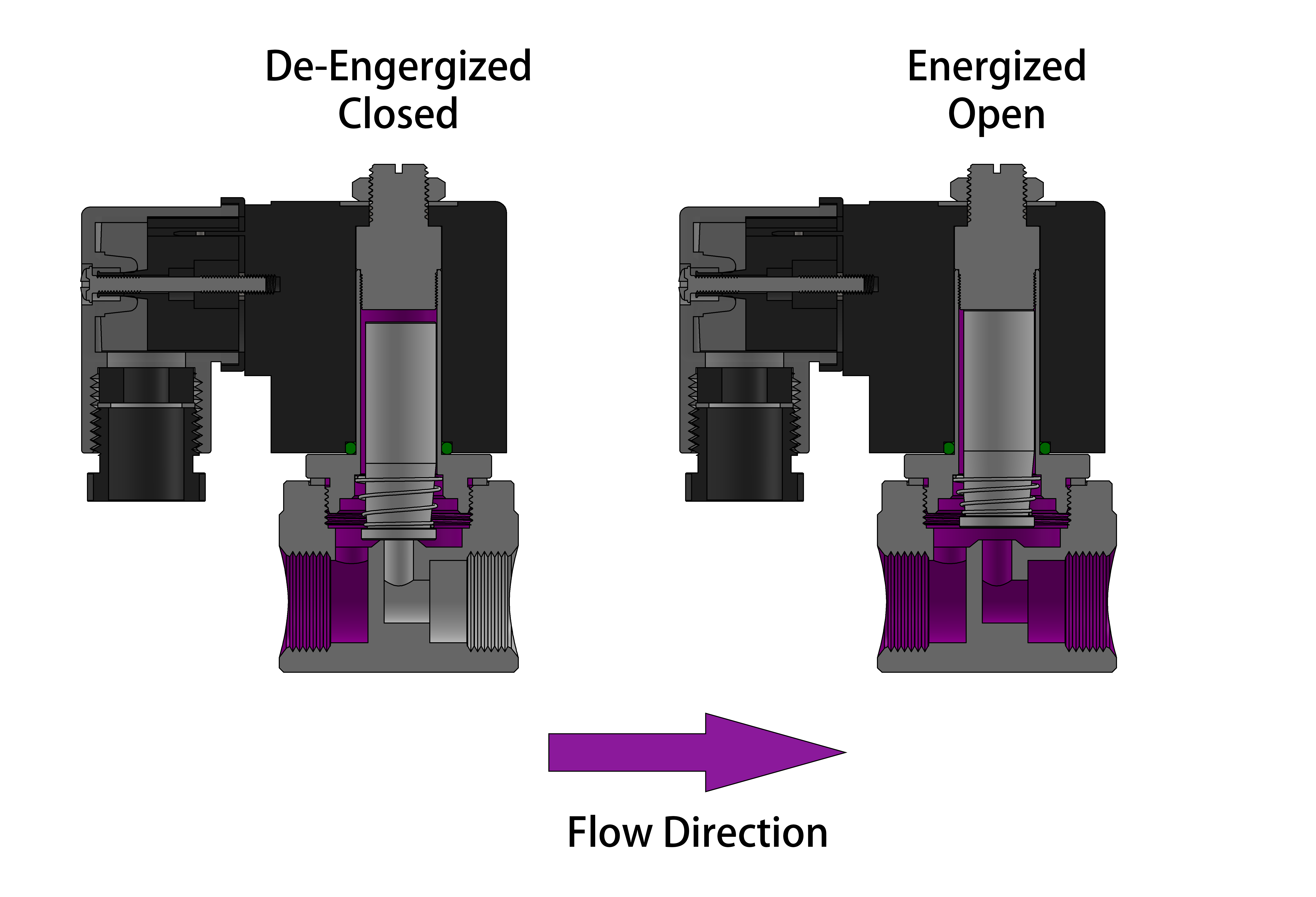
The 2S025-050 valves are direct acting solenoid valves that do not require a minimum
operating differential pressure. As shown in the diagram below, when the coil is de-energized (left diagram),
the plunger rests on the main orifice and is held in place by the plunger spring force, sealing the valve.
When the coil is energized (right diagram), the solenoid lifts the plunger and allows the working medium to
flow through the orifice. The working medium and flow direction are indicated in purple in the diagram.
ALL standard valves are supplied with Continuous Duty Coils of the proper class of insulation for the
service indicated on the valve. It is normal for the coil temperature may become hot after being energized for extended
periods. Smoke or burning odor indicates excessive coil temperature and the power should be disconnected to the coil
immediately.
SERVICE LIFE: The service life of the solenoid valve depends on the operating conditions such as
pressure, temperature, type of medium, and the voltage. Normally the STC solenoid valves are reliable
for 1 to 5 million cycles.
| Dimensions | ||||||

|
||||||
| 2E100-250 Series Solenoid Valve Dimensions | ||||||
| Model | Port | A | B | C | ||
| 2S025-1/4 | 1/4″ NPT | 80.4 | 28.2 | 34.5 | ||
| 2S035-1/4 | 1/4″ NPT | 82.1 | 29.5 | 41 | ||
| 2S040-3/8 | 3/8″ NPT | 84.7 | 32.5 | 41 | ||
| 2S050-1/4 | 1/4″ NPT | 84.7 | 32.5 | 41 | ||
| 2S050-3/8 | 3/8″ NPT | 84.7 | 74.2 | 80.0 | ||
| Dimensions for Reference Use Only: Units in mm | ||||||
Electrical Coil Connections
- To Connect a DIN Coil:
- Remove the Philips screw from the plastic housting & unplug from the DIN coil.
- Use the removed screw to push the terminal block out of the plastic DIN housing.
- Note the “1”, “2”, and ground “⏚” symbols.
- For DC DIN Coils, connect “1” to your positive lead and “2” to your negative lead.
- For AC DIN Coils, connect “1” to your HOT lead, “2” to your NEUTRAL lead, and “⏚” to your ground lead, if required.
- To Connect a Grommet Coil:
- For DC Coils, connect the red wire to your positive lead and the black wire to your negative lead.
- For AC Coils, connect the black wire to your HOT lead and the white wire to your NEUTRAL lead.
- For Coils provided with Molded Cables, the color of the wire indicates the type of lead:
- GREEN = Ground Wire
- BLUE = Positive or HOT Wire
- BROWN = Negative or Neutral Wire
Reviews
There are no reviews yet.