No products in the cart.
Shop all products

Solenoid Valve Specifications and Dimensions
people are viewing this right now
Guaranteed Safe Checkout

- Free worldwide shipping on all orders over $100
- Delivers in: 3-7 Working Days Shipping & Return
Call us at (650) 856-8833 or email us at Sales@StcValve.com.
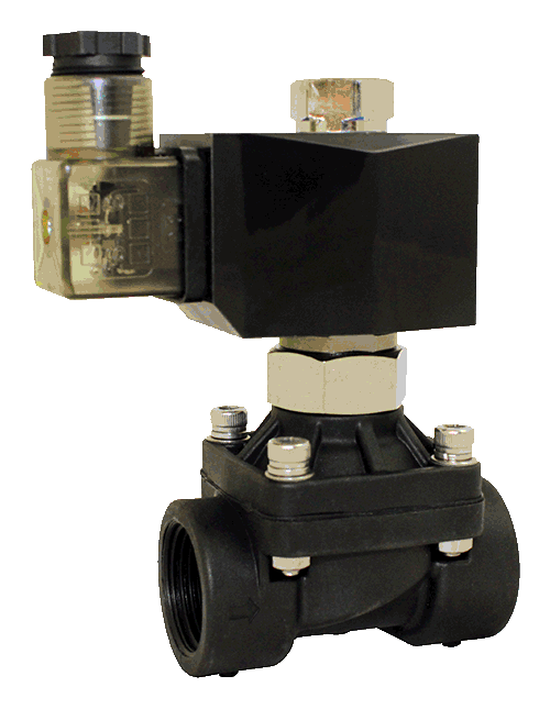
Solenoid Valve Specifications and Dimensions: 2P160-250 & 2PO160-250 Series
| Part No. | Valve Picture | Port Size (NPT) | Voltage | Electrical Connection | Description | Cv / Orifice | Power Consumption | Valve Symbol |
| 2P160-1/2 |
 |
1/2″ | 1 = 12VDC 2 = 24VDC 2A = 24VAC |
D = DIN |
Service: Air, Liquid, Oil, Water Direct Lift Diaphragm Normally Closed Two Way Diaphragm PA Plastic Solenoid Valve Temperature: 32 to 122°F (0 to 50°C) (with NBR Seal) Pressure: Vacuum to 90PSI Vacuum Reverse Flow Direction H Class IP65, 100% ED Coil Duty Voltage Tolerances: +10%-5% for DC, +10%-15% for AC |
Cv = 4.8 Orifice = 16mm |
12 to 20W |
|
| 2P200-3/4 | 3/4″ | Cv = 7.6 Orifice = 20mm |
||||||
| 2P250-1 | 1″ | Cv = 12 Orifice = 25mm |
||||||
| 2PO160-1/2 |
 |
1/2″ | 1 = 12VDC 2 = 24VDC 2A = 24VAC |
D = DIN |
Service: Air, Liquid, Oil, Water Direct Lift Diaphragm Normally Open Two Way Diaphragm PA Plastic Solenoid Valve Temperature: 32 to 122°F (0 to 50°C) (with NBR Seal) Pressure: Vacuum to 90PSI Vacuum Reverse Flow Direction H Class IP65, 100% ED Coil Duty Voltage Tolerances: +10%-5% for DC, +10%-15% for AC |
Cv = 4.8 Orifice = 16mm |
12 to 20W |  |
| 2PO200-3/4 | 3/4″ | Cv = 7.6 Orifice = 20mm |
||||||
| 2PO250-1 | 1″ | Cv = 12 Orifice = 25mm |
2P160-250 Series 2/2 Direct Lift Diaphragm Normally Closed Solenoid Valve:
This valve is a two-way, normally closed, direct lift, zero differential
solenoid valve. When the valve receives an electrical signal, a magnetic
field is formed which attracts the plunger covering the main orifice to
lift off, causing system pressure to drop. As system pressure on the top of
the diaphragm is reduced, full system pressure on the other side of the diaphragm
acts to lift the diaphragm away from the main orifice, which allows media to
flow through the valve. Since the bleed orifice is dimensionally smaller
than the pilot orifice, the system pressure cannot rebuild on the top of the
diaphragm as long as the pilot orifice remains open.
When the valve is de-energized, it releases its hold on the plunger. Then
the plunger forced by the spring drops and covers the main orifice. The
system pressure builds up on the top of the diaphragm through the bleed orifice,
forcing the diaphragm down until it covers the main orifice and stops media
flow through the valve.
2PO160-250 Series 2/2 Direct Lift Diaphragm Normally Open Solenoid Valve:
To Close: When the valve
is energized, the coil repels the plunger then the plunger covers the
main orifice. The system pressure builds up on the top of the diaphragm/piston
through the bleed orifice, forcing the diaphragm/piston down until it covers
the main orifice and stops media flow through the valve. When the system pressure
is 0PSI, the valve also can be operated.
To Open: When the valve is de-energized, the coil releases the plunger. The
plunger uncovers the pilot orifice causing system pressure holding the
diaphragm/piston closed to drop. As system pressure on the top of the
diaphragm/piston is reduced, full system pressure on the opposite side
of the diaphragm/piston acts to lift the diaphragm/piston away from the
main orifice, which allows the full media flow through the valve. When
the system pressure is 0PSI, the valve can be operated.
ALL standard valves are supplied with Continuous Duty Coils of the
proper class of insulation for the service indicated on the valve.
It is normal for the coil temperature may become hot after being
energized for extended periods. Smoke or burning odor indicates
excessive coil temperature and the power should be disconnected to
the coil immediately.
CAUTION: Do not energize the solenoid coil when it is not
installed onto the valve. It may cause it to overheat and create a
fire hazard.
SERVICE LIFE: The service life of the solenoid valve depends
on the operating conditions such as pressure, temperature, type of
medium, and the voltage.
Electrical Coil Connections
- To Connect a DIN Coil:
- Remove the Philips screw from the plastic housting & unplug from the DIN coil.
- Use the removed screw to push the terminal block out of the plastic DIN housing.
- Note the “1”, “2”, and ground “⏚” symbols.
- For DC DIN Coils, connect “1” to your positive lead and “2” to your negative lead.
- For AC DIN Coils, connect “1” to your HOT lead, “2” to your NEUTRAL lead, and “⏚” to your ground lead, if required.
- To Connect a Grommet Coil:
- For DC Coils, connect the red wire to your positive lead and the black wire to your negative lead.
- For AC Coils, connect the black wire to your HOT lead and the white wire to your NEUTRAL lead.
- For Coils provided with Molded Cables, the color of the wire indicates the type of lead:
- GREEN = Ground Wire
- BLUE = Positive or HOT Wire
- BROWN = Negative or Neutral Wire
|
2P Normally Closed |
2PO Normally Open |
 |
||||||||||
| Model: 2P160-250/2PO160-250 Series Solenoid Valve Dimensions | ||||||||||||
| Model | Port (NPT) | Cv | Orifice | A | B | C | D | E | F | W (lb) | ||
| 2P Series Normally Closed | 2PO Series Normally Open | 2P Series Normally Closed | 2PO Series Normally Open | |||||||||
| 2P160-1/2 2PO160-1/2 |
1/2″ | 4.8 | 16 | 100 | 113 | 51 | 115 | 128 | 74 | 36 | 60 | 1 |
| 2P200-3/4 2PO200-3/4 |
3/4″ | 7.6 | 20 | 95 | 108 | 51 | 115 | 128 | 70 | 36 | 60 | 1 |
| 2P250-1 2PO250-1 |
1″ | 12 | 25 | 105 | 118 | 65 | 125 | 138 | 87 | 36 | 60 | 1.2 |
| Dimensions for Reference Use Only: Units in mm | ||||||||||||
Related Products
Recently Viewed Products
Stainless Steel Needle Valve VNO1
$145.14 – $316.44
Male Branch Tee Swivel
$91.44
Reviews
There are no reviews yet.